F-22 Raptor filmed with a camera so fancy, you can see the vertical stabilizers get all wobbly
u/CleanDifference6455 — 5 hours ago
Hey everyone, I’m an 11th-grade student working on a nature-inspired overhaul of the Airbus Bionic concept. I ran my structural, cargo, and cabin concepts through an AI to generate a quick, punchy summary of my design ideas. [1]
I want to know where my physics or logistics break. Please tear this apart and help me figure out the engineering blind spots!
Where I need your help:
This simulation shows the initial pressure field development around a trailing edge. Edge thickness is 2mm on a foil of 1m chord. Streamlines give an idea of momentary flow direction at a given instant. It should be kept in mind that the pressure field changes rapidly and that a particular air particle might only move a very short distance before its underlying streamline again changes direction. This was part of an investigation into the time-dependent development of lift. Initial air movement creates a strong surface pressure disturbance, which refracts as a wave around the corners.
aerodynamics, lift, wing, airfoil, physics, sail, sailing
Hello, I just came across this video analyzing drone propellers using CFD simulations, and I thought it was really interesting. If anyone else is interested in the subject it's this one
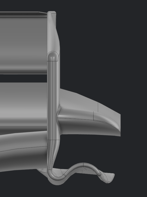
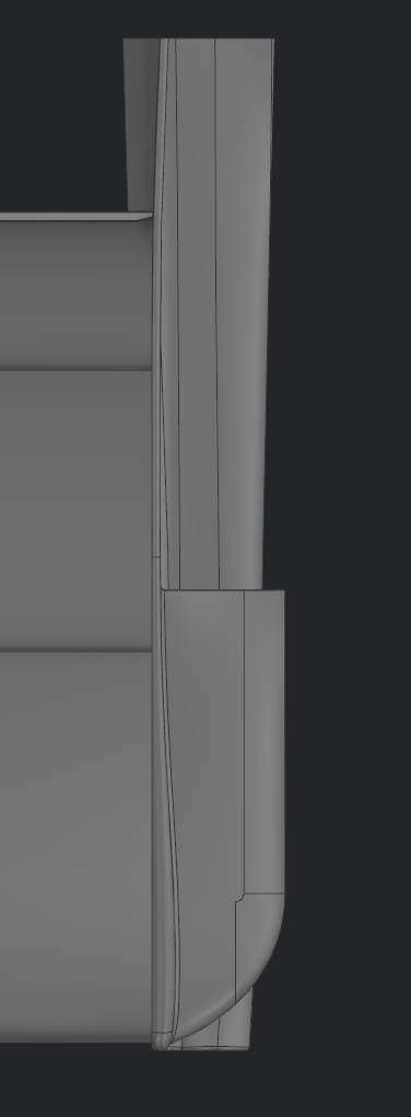
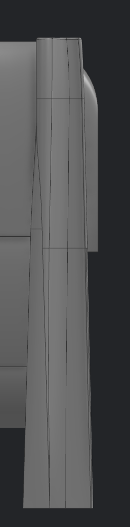
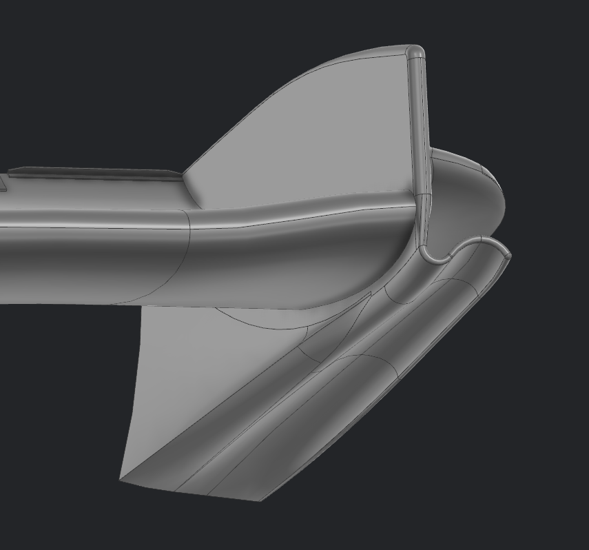
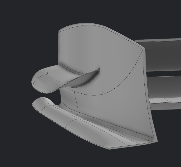
This is the front wing endplate of a FSAE car (USA rules) (straight line, 60kph).
This is a good number of iterations into a re-design. The inherent problem, in different locations to different extents, is preventing any vortex shed of the lower endplate/footplate from blowing up and dropping additional loss down the length of the car and decreasing the effective span of the front wing (ie preventing mass flow under the wing being significantly reduced with large blockage from blown up vortex). There is a lot of performance in the wing profiles from this, along with some additional load from the suction on the footplate.
This is what I have developed to so far. My intent is to start by spreading the vorticity across multiple edges/ reducing the pressure gradient over any single edge (bottom of endplate, outboard footplate curl, and slightly from the vane).
So far, somewhat irrespective of which way, I go, I continue to get this formation of loss and pink helicity on the outboard underside of the curl, which eventually blows up and compromises everything else.
I would like some help in understanding, aerodynamically, what are the driving factors in the flow field causing this, so that I could try to create and modify the geometry to prevent/mitigate it.
Thoughts so far:
I quite a lot of experience in surface design, so ability to make any geometry is not really a factor.
The only possibly relevant restrictions realistically are:
Basically the title. From my understanding lift is generated all along the wing, but boundary layer air is moving slower than freestream air in all the diagrams ane theory I've read online. Is flow decelerated below the wing to keep the pressure difference, or is pressure lift not significant once flow crosses peak acceleration and slows down, and then lift due to flow pushed down takes over?
what dictates that there shall be no relative velocity in the boundary layer? further, what if slipping actually does occur in regular subsonic flow over a wing at sea level?
Looked around on here everything came to a dead dead same with youtube videos they gave little instructions for it. So im looking to build active aero for our grassroots/enduro car wondering if yall can help me out with some pointers it was thinking of running it using active servos and linkage bars to adjust the wing itself. Which would hook up to a controller that is connected to the servo which would adjust the wing depending on speed and brake pressure. I guess the main issue im running into is the controller does anyone know if there is one preexisting or if I’ll have to build and program one?
Rough specs: ~2m class span, aspect ratio around 2, sweep roughly 60°/45° either side of an inboard crank, NACA 0004, fixed tricycle gear (or skids, not sure yet), single electric pusher prop, target all up weight in the low tens of kg. Elevon only pitch/roll, no tail surfaces, no rudder.
Questions I'd value input on:
Happy to share more (XFLR5/VSP screenshots, polar data) with anyone who has relevant tailless delta background.
Hi everyone,
I’m a fresh master’s graduate in Sustainable and Renewable Energy in Germany. My thesis was on wind turbine blade design, and since I started it early, I’m also finishing earlier than expected.
Do you have any recommendations on how to get into the wind energy industry in Germany? Any advice on companies, roles, networking, or skills to focus on would be appreciated.
Thanks!